<-- Home
|--matlab
|--FEM

Local_Meshing_Control_in_MATLAB中控制局部网格划分
网格划分控制
创造几何的方式
前面,我们对创造几何的方法进行了介绍:
- CSG几何体描述
- 预定义几何体中的
multicuboid函数,还有其他的比如multicylinder、multisphere等函数 - 几何函数描述2D区域
- STL文件导入,直接从外部几何文件导入
- 配合CSG、几何函数和预定几何性状,利用
extrude函数来产生3D几何
网格划分控制
在网格划分局部控制参数一节中,我们介绍了PDE工具箱中的网格划分中针对特定面、边和顶点的控制尺寸参数。
但是实际在应用中,设置参数是按照编号来进行的。因此,控制的局部必然要与几何中的顶点、边和面的构造结合在一起。
这里结合例子来分析如何控制局部网格划分。
编辑几何体方法
增加顶点的方法
Matlab PDE工具箱提供了addVertex函数来增加顶点。
1model = createpde();
2
3g = importGeometry(model, "Block.stl");
4
5pdegplot(g, "VertexLabels", "on", "FaceAlpha", 0.5);
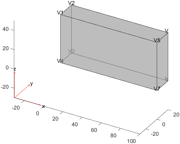
增加顶点:
1VertexID = addVertex(g, "Coordinates", [20 0 50]);
2% Add a vertex at (20, 0, 50), and return the vertex ID = 9
3pdegplot(g, "VertexLabels", "on", "FaceAlpha", 0.5);
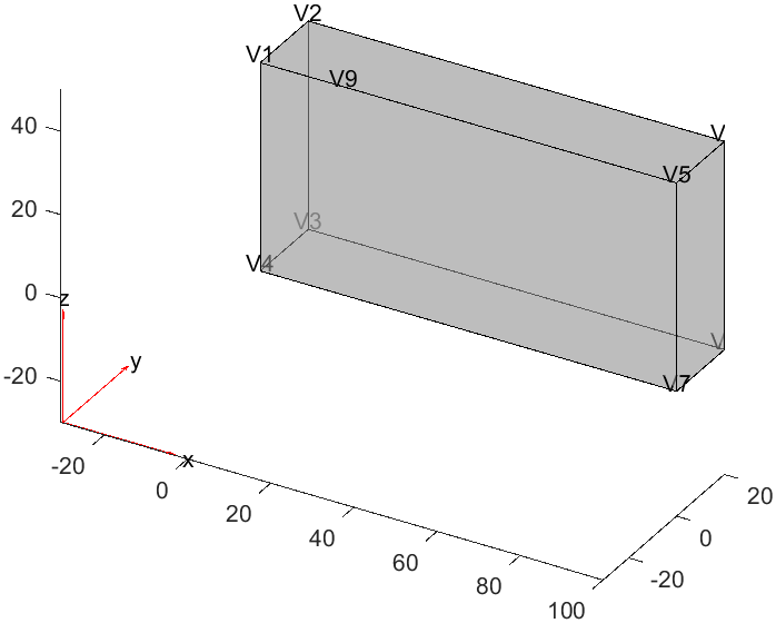
可以看到这里增加了一个顶点,这个顶点的编号为9,通过变量VertexID来访问。
这个时候,我们就能够通过这个顶点来控制局部网格划分。
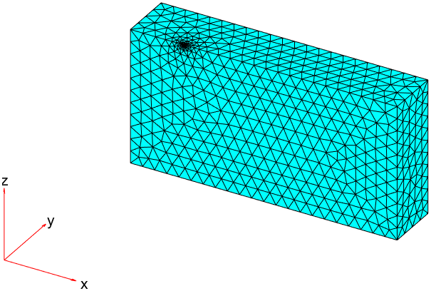
1generateMesh(model, "Hvertex", {VertexID, 0.1});
2pdeplot3D(model);
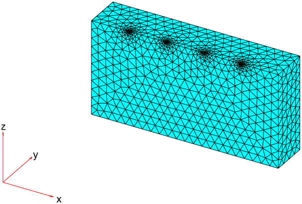
增加多个顶点
当然,增加多个顶点也不话下,同样可以通过addVertex函数来实现。
 1model = createpde();
 2
 3g = importGeometry(model, "Block.stl");
 4V = ([20 0 50; 40 0 50; 60 0 50; 80 0 50]);
 5VertexIDs = addVertex(g, "Coordinates", V); % Add vertices at (40, 0, 50), (60, 0, 50), and (80, 0, 50), and return the vertex IDs = 10, 11, 12
 6
 7figure(1);
 8pdegplot(g, "VertexLabels", "on", "FaceAlpha", 0.5);
 9exportgraphics(gcf, '../matlab-img/origin-geometry-4p.png')
10
11figure(2);
12generateMesh(model, "Hvertex", {VertexIDs, 0.1});
13pdeplot3D(model);
14exportgraphics(gcf, '../matlab-img/origin-geometry-4p-meshing.png')
可以看到增加的四个顶点的编号:
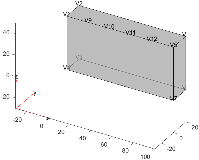
此时,通过设置尺寸参数就能够控制局部网格划分。
几何创建方法
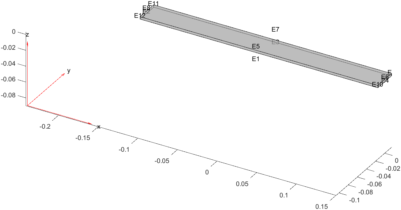
原始方案
首先,也就是在分析问题的时候,就确定可能会在哪些边界需要加强网格结构,在实现几何体的过程中,实现进行计算域的划分,产生实际的几何体组合,从而暴漏相应的边界。
假设我们要在一块直板的某个部分增加载荷,则事先就要把计算域在该位置增加额外的划分。
1%creation of the beam
2gm = multicuboid(0.3,0.03,0.003);
3model = createpde("structural","modal-solid");
4model.Geometry = gm;
5pdegplot(gm, "EdgeLabels", "on","FaceAlpha",0.5)
上面的几何体为一个完整的直板,我们可以通过pdegplot函数来查看其边界的编号。但是要在直板中间的某个位置增加网格划分,就必须增加名为Edge的实体。
Matlab提供了addVertex和addFace的函数,但是恰恰没有提供addEdge的函数。
思路前面给出了例子,在给定的直线上面增加很多个点,通过addVertex函数,在划分网格的时候,通过这些点来增加网格划分。
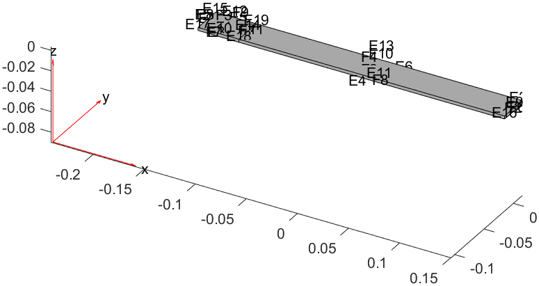
重回几何创建的迭代
或者,我们重新构造几何体,从物理上将计算域按照特殊条件的线划分为不同的区域,然后再进行网格划分。
1%Create the 3D geometry by extruding two adjacent rectangles
2gd = [3 4 -0.15 -0.11 -0.11 -0.15 -0.015 -0.015 .015 .015;
3 3 4 -0.11 0.15 0.15 -0.11 -0.015 -0.015 .015 .015]';
4dl = decsg(gd);
5gm = geometryFromEdges(dl);
6gm = extrude(gm, 0.003);
7%Create the model and add the geometry
8model = createpde("structural", "modal-solid");
9model.Geometry = gm;
10figure(1);
11pdegplot(gm, "EdgeLabels", "on", "FaceLabels", "on")
12
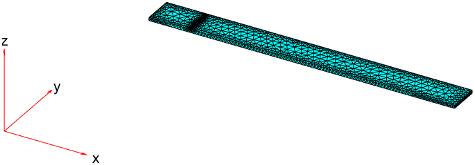
13figure(2);
14generateMesh(model, "Hedge", {14, 0.001})
15pdeplot3D(model);
新的几何提构造:
这样我们就能得到一个在直板中间的局部网格划分。
总结
- 工具箱提供了有限的节点增加方法,通过增加节点来控制局部网格划分。
- 最好还是在分析之初,或者在迭代过程中回到几何创建的过程中,来额外产生边和面,从而控制局部网格划分。
文章标签
|-->matlab |-->FEM |-->meshing
- 本站总访问量:loading次
- 本站总访客数:loading人
- 可通过邮件联系作者:Email大福
- 也可以访问技术博客:大福是小强
- 也可以在知乎搞抽象:知乎-大福
- Comments, requests, and/or opinions go to: Github Repository